Aerospace Capstone Project
Two Semesters of Research
The Aerospace (Astronautics) Capstone at ASU had student teams of 6 set out to research and conceptualize spacecraft set to accomplish any task that they wanted. In our group's case, we chose to design a system that would go into Low Earth Orbit to capture derelict spacecraft and bring it back to Earth unharmed. In congruence with recent trends, we also designed the vehicle to be reusable. We felt that this would provide us with enough of a challenge to design while still being feasible due to the amount of documented operations in LEO.
Our design takes inspiration from a number of different spacecraft, while also implementing novel solutions to common problems. The thrusters and general shape of the vehicle are based on Stoke Space's Hopper 2 due to it's demonstrated reusability, and the capture arm is a scaled down re-implementation of the ISS Canadarm. We also borrowed from SpaceX's Starship and the NASA Space Shuttle program by using composite insulation tiles for the heatshield, and the reentry parachute system is modeled with NASA's Orion mission as a point of reference.
My Part in This
I was personally responsible for designing the Thermal Control and Reentry subsystems. This involved the radiators, heat shielding, and parachutes. I also took on a more systems-engineering related role by creating the physical architecture diagram, system performance requirements, and requirments verification plan.
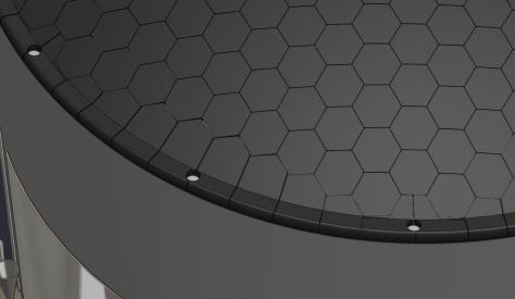
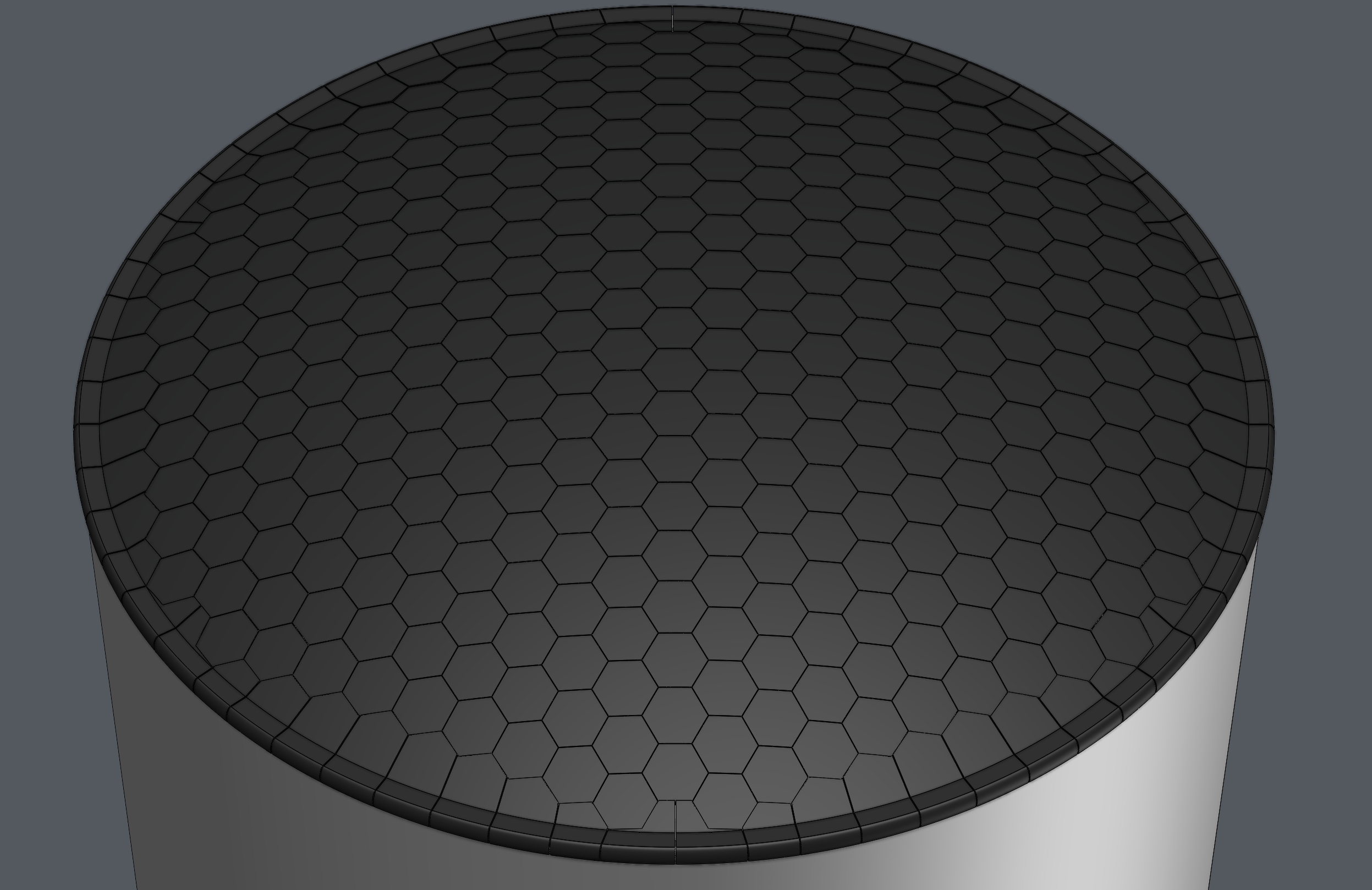
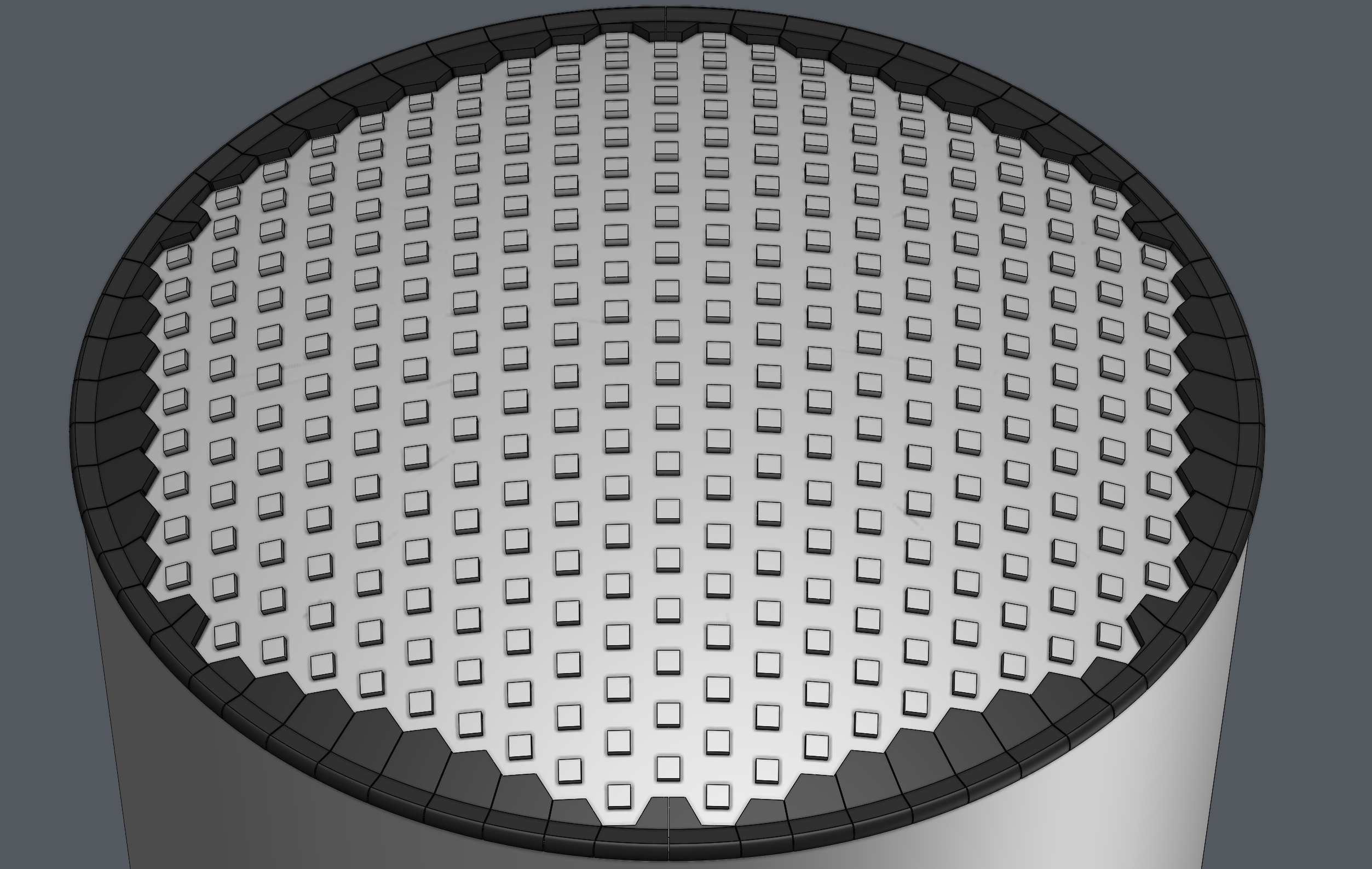
The heat shield uses 6 unique designs for 381 tiles in total, 321 of which are hexagons. The remaning 5 tile designs are repeated along the edge of the hexagonal shape to fill out the greater circular profile. These tiles are designed to made of sintered silica fiber with a layer of borosilicate reaction cured glass covering the surface, similar to what was used on the NASA Space Shuttle missions.
At the early stage of the design, the team wasn't certain about the exact sizing and power usage the system was going to need - both of which are key variables when determining the sizing for the radiators. To circumvent this problem, I created a tool in MATLAB that estimated the bulk temperature of the spacecraft given these two variable inputs. This way, the base calculations for the radiator sizing could be considered as already done - and only required a bit of plug and play to get going.
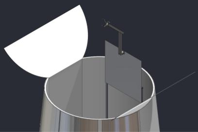
The radiators have two sections - the bulk of it is placed on the surface of the spacecraft itself, while the other section is attached to the inner section of the payload bay doors. This acts as a pseudo-deployable section for use when the vehicle is in direct sunlight.
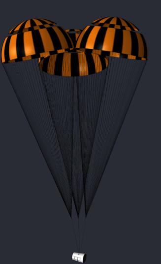
The parachute design takes heavy inspiration from NASA's Orion mission and involves 3 sets of chutes. The 1st set contains 2 drogue chutes dedicated to stabilizing the spacecraft and minimizing any spin. The 2nd set will have 3 pilot chutes which serve to pull out the next set of 3 main parachutes measuring 52.88m in diameter.
This physical architecure diagram shows three methods of interfacing between every subsystem. Those are the Power, Data, and Thermal Control connections - which are represented by the Red, Blue, and Orange lines, respectively.

Team Members
This project was completed by Kevin Nguyen, Jose Parra, Brent Holmes, Katie Herrington, Jacob Countryman, and myself with guidance from Professor Boehmer and Frederick Garrett.